
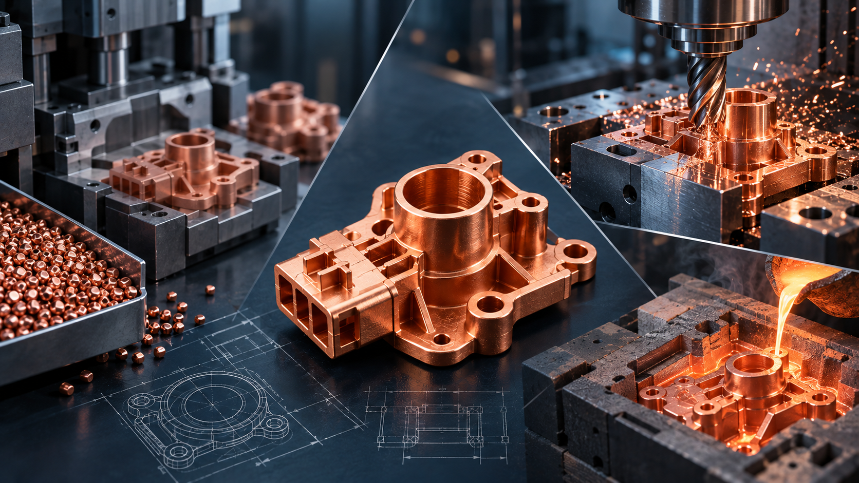
Complex copper parts become harder to manufacture efficiently when the design combines intricate geometry, tight local features and repeated production. CuMIM®, CNC machining and casting all shape copper differently, so the manufacturing route affects material use, feature design, tolerances and scalability.
CuMIM® stands out when a relatively small copper component needs detailed geometry to be reproduced repeatedly at higher volumes. Instead of cutting each feature from solid stock or relying on molten-metal solidification, CuMIM® forms the geometry from pure-copper feedstock before debinding and sintering.
How Do CuMIM®, CNC Machining and Casting Shape Copper Differently?
The biggest difference is how the final geometry is created. That difference drives many of the practical trade-offs later in production.
Process | How the part is formed | Manufacturing implication |
CuMIM® | Pure-copper feedstock is injection molded, debound and sintered. | Complex and integrated features can be formed in the mold; sintering shrinkage is planned into tooling and process development. |
CNC machining | Material is removed from solid copper stock. | Geometry is limited by cutting-tool access, and complex parts may require multiple setups or machining steps. |
Casting | Molten metal solidifies inside a mold or investment cavity. | Capability depends on the casting method; fine features, shrinkage and dimensional control are influenced by the solidification process. |
What Are the Main Copper MIM Advantages?
The main copper MIM advantages come from creating more of the final geometry during molding rather than adding complexity through repeated downstream operations.
- Complex three-dimensional geometry can be formed during molding.
- Multiple features may be integrated into a single component, supporting part consolidation and fewer assembly steps.
- Less material may need to be removed than in heavily machined designs.
- The same tooling can reproduce the geometry repeatedly once the process is established.
- Copper’s thermal or electrical function can be combined with intricate molded geometry.
AMT’s CuMIM® technology is designed for complex pure-copper components used in thermal-management applications. With a thermal conductivity of 320 W/mK, CuMIM® combines copper’s thermal performance with the design flexibility and scalability of Metal Injection Molding. To date, AMT has delivered more than five million copper components for related applications.
CuMIM® vs CNC Machining: Where Does CuMIM® Gain an Advantage?
In a CuMIM® vs CNC machining comparison, the advantage of CuMIM® becomes more visible as geometry requires more machining steps and the same part must be produced repeatedly at scale.
Manufacturing issue | CuMIM® approach | CNC machining implication |
Complex features | Features can be built into the molded geometry. | Pockets, difficult-to-access surfaces or intricate features may require extra setups, specialist tooling or additional operations. |
Material use | Near-net-shape production limits the amount of copper that must be removed to reach final geometry. | Material is removed from solid stock; waste increases when a large portion of the starting copper must be machined away. |
Production scale | Once tooling and the process are established, the same geometry can be repeated at higher volumes. | Each component still requires individual machining time, so machine utilisation and cycle time remain part of the production cost. |
Part consolidation | Several features can be integrated into one molded part. | Complex assemblies may require separate machined features, parts or operations. |
Critical dimensions | Selected high-precision features can still be machined after sintering. | Precision is created through machining across the required features. |
There is no fixed production quantity where every machined copper part should move to CuMIM®. The crossover depends on geometry, the number of machining operations, copper material cost, tolerance requirements, tooling investment, annual volume, secondary processing and inspection.
A simple copper plate at low volume may not justify dedicated CuMIM® tooling. By contrast, a small component with several pockets, mounting features or difficult-to-access surfaces can become a stronger CuMIM® candidate as production scales. Where only a few bores, mating surfaces or interfaces need tighter control, CuMIM® can form the overall part and secondary CNC machining can be reserved for those selected features.
CuMIM® vs Casting: What Changes for Smaller, Intricate Copper Parts?
CuMIM® vs casting is not simply a comparison between two near-net-shape processes. CuMIM® uses powder metallurgy, molding, debinding and sintering, while casting starts with molten metal and solidification. Those different material routes affect the type of geometry and dimensional control involved.
Feature size and detail. CuMIM® is well suited to smaller, intricate and integrated features. Casting can also form complex shapes, but fine-feature capability depends strongly on the specific casting method.
Part size. CuMIM® is most attractive for relatively small components, while casting covers a broader range of larger part sizes.
Dimensional control. CuMIM® sintering shrinkage is predicted and controlled through tooling and process development. Casting must manage solidification shrinkage and distortion.
Production strategy. CuMIM® is strong when the same small, complex geometry is repeated at scale. Casting capability varies across methods, part sizes and production volumes.
Casting is a broad category that includes sand casting, investment casting, permanent-mold casting and die casting, each with different tooling, tolerance, size and material capabilities. For smaller, detail-rich copper components, CuMIM® offers a route that combines fine molded geometry with repeatable production. Selected critical dimensions can still be machined after the primary forming process when required.
How Do Material Use and Tolerances Affect the Decision?
Material use and tolerance strategy should be reviewed together rather than treated as separate decisions. CuMIM® is a near-net-shape process, so less copper is typically removed to reach the final geometry. CNC machining starts from solid stock, so material removal increases with heavily machined designs. Casting is also near-net-shape, although gates, runners or risers may need to be removed depending on the method.
For dimensional control, CuMIM® shrinkage is planned into the tooling and process, while casting must account for solidification and cooling. If only a small number of features require machining-level precision, those features can be finished after CuMIM® rather than defining the manufacturing route for the entire component.
When Is a Copper Part a Strong CuMIM® Candidate?
CuMIM® becomes a stronger production option when several of the following conditions appear in the same part:
- The component is relatively small but geometrically complex.
- The design contains pockets, thin sections, internal features or areas that are difficult for cutting tools to access.
- Several features or separate components can potentially be consolidated into one molded part.
- A heavily machined version removes a large amount of copper from the starting stock.
- The same geometry must be reproduced repeatedly at higher production volumes.
- Only selected dimensions need secondary machining or tighter local control.
Reviewing geometry, tooling, annual volume, secondary operations and inspection together gives a clearer picture of where CuMIM® can reduce manufacturing complexity.
Design the Manufacturing Route Around the Part
CuMIM®, CNC machining and casting create copper parts in fundamentally different ways. For small, complex copper components that need to be reproduced consistently at scale, CuMIM® can bring several requirements together in one route: intricate molded geometry, reduced material removal, part consolidation and repeatable production.
The strongest CuMIM® applications are therefore not defined by one feature alone. They are parts where geometry, material use, production volume and tolerance strategy all point toward forming more of the component during molding and limiting secondary operations to the features that truly need them.
AMT can review the component geometry, material requirements, critical dimensions and expected production volume to determine whether CuMIM®, secondary machining or a combined route is appropriate.
Frequently Asked Questions
What types of copper parts are good candidates for CuMIM®?
CuMIM® is especially relevant for relatively small copper parts with complex geometry, difficult-to-access features, opportunities for part consolidation and repeatable higher-volume production. It is particularly worth evaluating when a machined design would require significant material removal or several separate operations.
Can CuMIM® reduce the amount of CNC machining required?
Yes. CuMIM® can form much of the component geometry during molding, so machining can be reserved for selected critical dimensions, bores, mating surfaces or other features that need tighter local control.
How does CuMIM® use copper differently from CNC machining?
CuMIM® is a near-net-shape process, so relatively little copper is removed to reach the final geometry. CNC machining starts from solid stock and removes material, which can become significant for heavily machined or intricate parts.
How does CuMIM® compare with casting for smaller, detailed copper components?
CuMIM® uses metal powder, injection molding, debinding and sintering, while casting forms parts from molten metal. For smaller, detail-rich copper components, CuMIM® can combine intricate molded features with repeatable production, while casting capabilities depend strongly on the specific casting method, part size and geometry.
Does CuMIM® eliminate the need for secondary machining?
Not always. Secondary machining may still be used for selected features that require tighter tolerances or specific functional surfaces. The advantage is that the overall part geometry can be formed through CuMIM®, limiting machining to the features that truly need it.


