
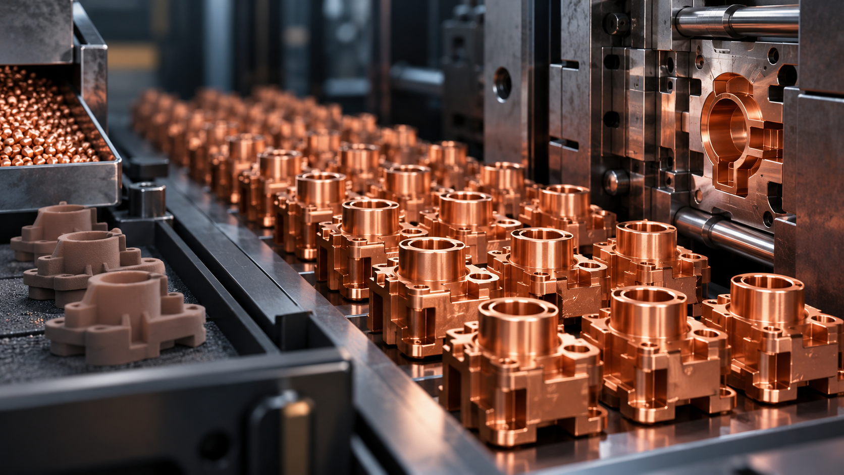
Copper Injection Molding (CuMIM®): A Manufacturing Guide for Complex, High-Volume Copper Parts
Copper is valued for its thermal and electrical conductivity, but complex copper parts can become time-consuming and material-intensive to machine at scale.
Copper injection molding (CuMIM®) offers another route. It combines the shaping flexibility of injection molding with pure copper, making it useful when a part needs complex geometry, repeatability and higher-volume production.
What Is Copper Injection Molding (CuMIM®)?
Copper injection molding, or CuMIM®, is a metal injection molding process in which pure-copper feedstock is molded into shape, debinded and sintered to produce the final component.
Instead of machining most features one by one from solid copper, CuMIM® forms much of the geometry during molding. This can reduce machining for suitable designs while allowing complex features to be repeated consistently.
How Does the CuMIM® Process Work?
The CuMIM® process follows five core stages:
Stage | What Happens |
1. Feedstock preparation | Fine copper powder is combined with a binder to create a moldable feedstock. |
2. Injection molding | The feedstock is injected into a precision mold to form the required geometry. |
3. Debinding | Most of the binder is removed while the molded part keeps its shape. |
4. Sintering | Copper particles bond and densify under controlled heat as the part shrinks toward its final dimensions. |
What CuMIM® Materials Should Engineers Consider?
CuMIM® material requirements should be reviewed around the final function of the part, including thermal, electrical, dimensional and mechanical requirements.
Pure copper is used where thermal or electrical performance is a priority. Final performance should be evaluated against the part’s thermal, electrical, dimensional and mechanical requirements.
Design Requirement | What to Review |
Thermal performance | Thermal conductivity needed to meet end design’s heat-dissipation target. |
Electrical performance | Electrical conductivity needed to meet current-carrying and resistance target. |
Part geometry | Thin-wall sections, internal channels and hard-to-access features can be difficult to machine. CuMIM® can form these features more efficiently while reducing secondary machining. |
|
|
What Affects Copper MIM Thermal Conductivity?
- Material composition and purity influence thermal and electrical behaviour.
- Density and remaining porosity affect how efficiently heat moves through the component.
- Sintering temperature, atmosphere, time and process control influence the final material properties.
- Part geometry matters because good conductivity alone does not guarantee efficient thermal performance.
For engineering evaluation, use verified data for the specific CuMIM® material and process rather than assuming every molded copper component will perform like bulk copper.
Why Use CuMIM® for Complex, High-Volume Copper Parts?
CuMIM® becomes most relevant when complex geometry and repeatable production volume need to work together.
- Complex three-dimensional geometry and integrated features
- Repeatable medium-to-high-volume production
- Part consolidation that may reduce assembly steps
- Less material removal compared with heavily machined designs
- Fewer machining operations for suitable features
- Integration of thermal or electrical functions into the component design
CuMIM® vs CNC Machining: Which Is Better for Copper Parts?
For complex copper components produced at scale, CuMIM® can offer significant advantages over conventional CNC machining. By forming multiple features in a single molding process, CuMIM® can reduce machining operations, improve material utilisation and support consistent high-volume production.
Consideration | CuMIM® | CNC Machining |
Complex geometry | Forms complex shapes and multiple features within a single molded component | Complex geometries may require multiple setups, machining steps or specialised tooling |
Production volume | Well suited for repeatable medium-to-high-volume production | Machining time increases with production quantity, making large-volume production less efficient |
Material utilisation | Near-net-shape process with minimal material removal. | Significant material may be removed from solid copper stock, resulting in higher material waste |
Part consolidation | Multiple features can be integrated into a single component, reducing secondary operations and assembly | Complex designs may require additional machining operations or multiple individual components |
Production efficiency | Multiple parts can be produced repeatedly using the same tooling | Each part requires individual machining time, which can limit production throughput |
Cost at scale | Tooling investment can be distributed across higher production volumes, reducing per-part cost | Cost remains heavily influenced by machining time, machine utilisation, tooling and material removal |
Design complexity | Enables complex 3D geometries that may be difficult or costly to machine | Tool access and machining limitations can restrict certain internal or intricate geometries |
For copper components requiring complex geometry, high material utilisation and scalable production, CuMIM® can reduce machining steps, material waste and per-part processing costs compared with conventional CNC machining.
Where Is CuMIM® Used?
CuMIM® applications are most relevant where copper performance, compact geometry and production scale need to work together.
CuMIM® Applications | Why CuMIM® Can Be Relevant |
Thermal management & electronics | Complex copper shapes can be designed around compact heat-generating electronics. |
Optical / high-speed communication | Compact thermal parts can fit around dense optical and electronic hardware. |
Automotive electronics | Complex copper components can support thermal needs within limited packaging space. |
High-volume precision components | Useful where repeatable geometry is needed together with thermal or electrical function. |
When Should You Consider Copper Injection Molding?
Copper injection molding is worth evaluating when a component needs copper’s functional properties, complex geometry and repeatable production at meaningful volume.
- The part contains several complex or difficult-to-machine features.
- Current production needs multiple machining operations.
- Material removal is significant.
- Production volume is expected to increase.
- Part-to-part consistency is important.
- Several features or separate parts may be consolidated into one component.
CuMIM® may be less attractive for very simple geometries, very low quantities or parts that are already produced efficiently by conventional methods.
Frequently Asked Questions About CuMIM®
What is Copper MIM?
Copper MIM is another way to describe copper injection molding (CuMIM®), where pure-copper feedstock is injection molded, debound and sintered to create the final metal component.
What types of parts are suitable for CuMIM®?
CuMIM® is most attractive for parts that combine complex geometry, repeatability and medium-to-high production volumes, especially when machining the same geometry would require several operations.
Is CuMIM® suitable for thermal-management applications?
Yes, it can be considered where copper’s thermal properties and complex geometry are both important. Final performance still depends on the material, density, design and manufacturing process.
Can CuMIM® parts be machined after sintering?
Yes. Secondary machining can be used for selected dimensions, surfaces or interfaces that require tighter control.
Is CuMIM® always better than machining?
CuMIM® becomes more relevant when geometry and repeatable production scale justify tooling and process development.
Choosing the Right Manufacturing Route
The value of CuMIM® comes from combining material performance, design complexity and production scalability. The right choice should be based on the part’s geometry, tolerances, material requirements, production volume and final function.
If you are evaluating a copper component for CuMIM®, AMT can review the design, critical tolerances, material requirements and expected production volume to determine an appropriate manufacturing approach.


