
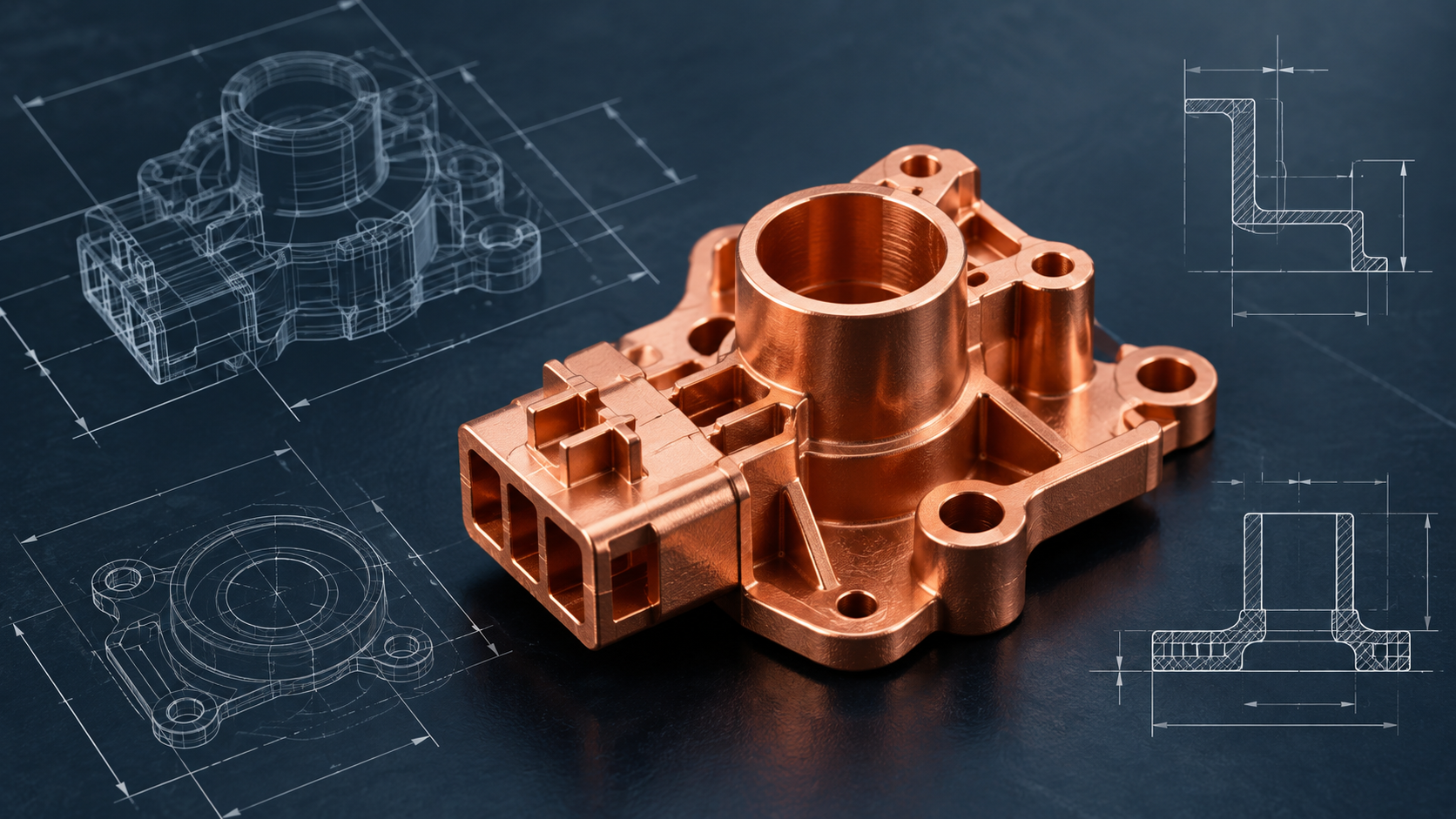
Successful CuMIM® design starts well before production. Material selection is important, but geometry, tolerances, wall thickness and feature design must also be considered across molding, debinding and sintering.
Applying practical copper MIM design guidelines early can improve manufacturability, support dimensional control and reduce unnecessary secondary operations. An experienced CuMIM® manufacturer should work with the design team during DFM, helping optimize the part before production tooling is finalized.
What Should Engineers Consider When Designing a Copper MIM (CuMIM®) Part?
A well-designed CuMIM® component balances function, geometry, tolerances, material performance and production requirements across the complete manufacturing process.
- Critical dimensions and functional surfaces
- Wall thickness and changes in section
- Unsupported or cantilevered features
- Holes and internal features
- Areas that may require secondary machining
- Thermal or electrical requirements
- Expected annual production volume
What Copper MIM (CuMIM®) Tolerances Can Be Achieved?
Achievable copper MIM tolerances vary with part geometry, component size, material, tooling and post-sintering requirements. Rather than applying one tolerance across every feature, the design should identify which dimensions are truly critical to fit, function and assembly.
For general MIM applications, dimensional tolerances of approximately ±0.3% to ±0.5% provide a useful design reference. Selected critical features may be controlled more tightly depending on geometry, material, tooling and process requirements.
For CuMIM® components, the final tolerance strategy should be established during DFM based on the part design and functional requirements.
Why Does Geometry Matter in Copper MIM (CuMIM®)?
Geometry plays a major role in mold filling, debinding, sintering shrinkage and dimensional stability. A feature that appears straightforward in CAD may behave differently during the CuMIM® process, which is why early DFM review is important.
Copper MIM Design Guideline | Why It Matters |
Keep wall thickness consistent | More consistent wall sections can support stable molding and sintering, while abrupt thick-to-thin transitions may increase dimensional variation. |
Use thin walls carefully | For general MIM designs, approximately 0.7 mm is a useful reference, while sections around 0.3 mm may be achievable for suitable geometries. Final CuMIM® limits should be confirmed during DFM. |
Support long or cantilevered features | Ribs or other supporting features can improve shape stability and help control distortion during sintering. |
Review holes and small features | Feature size, orientation and function all influence manufacturability. Critical holes, press-fit areas or precision interfaces may require design optimization or secondary machining. |
Plan for sintering shrinkage | Sintering shrinkage is part of the process and should be accounted for during tooling design and process development. |
When Should a Copper MIM (CuMIM®) Manufacturer Get Involved?
Involving a CuMIM manufacturer early in the design process can improve manufacturability and reduce costly changes after production tooling is released.
A Design for Manufacturing (DFM) review helps determine which features can be molded directly, which may benefit from redesign or consolidation, and which should remain as secondary machining operations. This is especially valuable when converting a CNC-machined copper component to CuMIM®, where the design can be optimized for molding rather than simply copied from the machined version.
AMT supports Early Supplier Involvement, DFM proposals and mold-flow simulation to help optimize CuMIM® components during product development.
How Do You Choose a Copper MIM (CuMIM®) Manufacturer?
Choosing the right CuMIM® manufacturer involves more than comparing quotations. Look for a supplier with experience in pure-copper material behavior, tooling, molding, debinding, sintering, dimensional control and the secondary processes required to meet the final component specification.
What to Check | What a Strong Supplier Should Demonstrate |
CuMIM® & material expertise | Experience with pure-copper feedstock and the ability to connect process design with thermal, electrical and mechanical performance requirements. |
DFM support | Structured review of geometry, wall thickness, critical tolerances, mold flow and any required secondary operations. |
Tooling capability | Strong coordination across mold design, fabrication, engineering changes and MIM process development. |
Sintering experience | Understanding of how geometry, support strategy, material behavior and furnace conditions influence density and dimensional control. |
Secondary manufacturing | Capability to support or coordinate machining, finishing, testing and inspection where required. |
Quality systems | Quality systems, documentation and traceability aligned with the requirements of the target industry and application. |
AMT combines in-house MIM mold design and fabrication with DFM support and a range of secondary operations, including CNC machining, grinding, turning, lapping, heat treatment, plating, finishing, testing and inspection. AMT also holds ISO 9001, ISO 13485, ISO 14001 and IATF 16949 certifications to support quality-focused manufacturing requirements.
Copper MIM (CuMIM®) Design Checklist
Question to Ask | Why It Matters |
Which dimensions are functionally critical? | Helps focus tighter tolerances only where they are needed for function or assembly. |
Is wall thickness reasonably consistent? | Supports more consistent molding, sintering and dimensional control. |
Are there unsupported sections? | May require ribs or other supporting geometry to improve shape stability during sintering. |
Can multiple components be combined? | Can reduce part count, joining steps and assembly complexity. |
Which surfaces need secondary machining? | Helps define the manufacturing route, tolerance strategy and cost earlier in development. |
What thermal or electrical performance is required? | Helps align material and process choices with thermal or electrical performance needs. |
What is the expected annual volume? | Helps determine whether CuMIM® is a suitable production route from both technical and economic perspectives. |
Design for the Process, Not Just the Drawing
Copper MIM design guidelines provide a practical starting point, but tolerance, wall thickness, geometry and sintering behavior must be considered together. Final design decisions should reflect the component’s material requirements, function and expected production volume.
A capable CuMIM® manufacturer should support the full path from material selection and DFM through tooling, process development, dimensional control and secondary operations. AMT can review copper component geometry, critical tolerances, material requirements and production volume to help determine an appropriate manufacturing approach before the design is finalized.
Frequently Asked Questions About Copper MIM Design
What tolerance can copper MIM achieve?
Copper MIM tolerances vary with geometry, component size, material and process requirements. AMT’s general MIM reference is approximately ±0.3% to ±0.5%, while final CuMIM® tolerances should be confirmed during DFM for the component’s critical dimensions.
What is the recommended wall thickness for CuMIM®?
For general MIM design, approximately 0.7 mm is a typical wall-thickness reference, with thinner sections possible for suitable geometries. Final CuMIM® wall thickness should be confirmed during DFM.
What are the main copper MIM limitations?
Key considerations include tooling investment, sintering shrinkage, geometry-dependent tolerances and secondary machining for selected high-precision features.
Can a machined copper part be converted directly to CuMIM?
In many cases, yes. However, the best results usually come from optimizing the component for CuMIM® rather than reproducing the CNC-machined geometry exactly.
How should I choose a CuMIM® manufacturer?
Look for pure-copper material expertise, strong DFM and tooling support, controlled sintering, dimensional validation, quality systems and secondary-process capability.


